Automated Keurig Water Refiller
- Jon Peroutka
- Mar 9, 2024
- 5 min read

Updated: May 24, 2025
After I purchased a Keurig coffee machine to make the groggy morning chore of making my coffee an easier task, I found myself refilling the water reservoir for it almost daily. This did not make me happy. While the overall task of making coffee was easier than with using a drip coffee maker, the chore of refilling the reservoir was one that felt very possible to automate.
I started by looking online for any solutions for this problem. The only solutions I found were ones which tapped the water line directly into the reservoir and were controlled either manually by a twist valve or by a float valve. Manually refilling the water reservoir with a twist valve didn't feel safe as I knew at some point I would end up turning on the valve, walking away for a moment, and then flooding my kitchen. Alternatively, the solution with the float valve was also tempting, but I've had float switches get stuck in the past. And just like the twist valve solution, I was worried that a continuous supply of water flowing over my countertops and floors was an event best qualified with a "when" rather than an "if."
Therefore, I undertook an endeavor for develop a digital solution which built in the safety mechanisms needed to allow me to sleep well at night knowing that I wouldn't wake up to a flooded kitchen. I started by developing a conceptual model of the design and components I thought might be needed (note the image below was refined throughout the project).

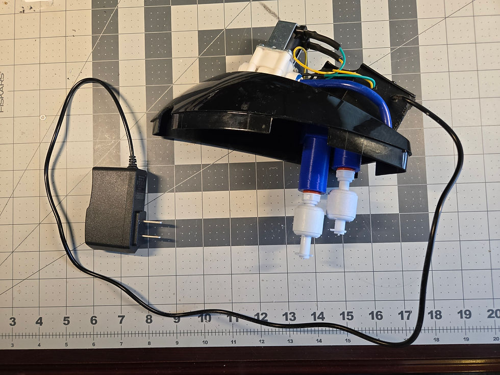
The design created includes 2 float switches to monitor the water level in the water reservoir. The lower switch sends a signal to the Arduino board and then to the relay which controls the solenoid to turn the flow of water on or off. The higher float switch is a safety mechanism in case the lower float switch fails for any reason and keeps water flowing errantly. If the higher float switch raises due to the water level, it sends a signal to the Arduino board to sound an alarm and lights the LED red. It simultaneously and wirelessly sends a MQTT message to my Home Assistant server over WiFi which then sends a notification to my phone (see image below), as well as turns off the WiFi smart switch which the whole unit is plugged into (effectively turning everything off).

My phone is set up to sound a non-stop alarm whenever a notification of this type comes in.
I'm particularly satisfied with the degree of security this system brings. Realistically, if anything was to go wrong with the system, I would likely be standing right next to the Keurig to react immediately (I'm also the only one living in the house who drinks coffee). However, if a guest was to use the Keurig or anyone else does something which causes the water to keep flowing, I would be alerted even if I wasn't nearby, and the system would autonomously turn itself off by switching the smart switch off.
All of the coding was done in C++ on the Arduino platform by myself. No ChatGPT or no Github Copilot was used! See the code below (note, I'm not a formally trained programmer, so I'm sure the code is ugly and does not follow best practices; take it as it is!).
#include <WiFi.h>
#include <PubSubClient.h>
#include <ESP32Ping.h>


//Set the LED light to pin 8
const int solenoid = 21;

//Set the float sensor to pin 3
int High_Float_Switch = 2;
int Low_Float_Switch = 3;
int speaker = 20;
int conn_status = 0;

//Set the RGB LED's pins
const int PIN_RED = 10;
const int PIN_GREEN = 9;
const int PIN_BLUE = 8;

WiFiClient wifiClient;
PubSubClient client(wifiClient);

const char ssid[] = "<insert Wifi name here>";
const char password[] = "<insert wifi password here>";

const char broker[] = "<insert broker IP address here>";
const char broker_user[] = "<insert broker username here>";
const char broker_pass[] = "<insert broker password here>";
int        port     = 1883;
const char topic[]  = "keurig";

int mqtt_counter = 1;


void setup() {
  //Serial.begin(115200);
  //while(!Serial);
  //Serial.println("Serial started.");
  pinMode(solenoid, OUTPUT);
  pinMode(High_Float_Switch, INPUT_PULLUP);
  pinMode(Low_Float_Switch, INPUT_PULLUP);
  pinMode(speaker, OUTPUT);
  pinMode(PIN_RED, OUTPUT);
  pinMode(PIN_GREEN, OUTPUT);
  pinMode(PIN_BLUE, OUTPUT);

  //Serial.println();
  //Serial.println();

  wifiConnect();

  //Serial.println("Device Initialized.");

}


void loop() {

 client.loop();

 if(digitalRead(Low_Float_Switch) == LOW && digitalRead(High_Float_Switch) == LOW){
    digitalWrite(solenoid, HIGH); //Open solenoid
    //Serial.println("Low switch Low, opening solenoid");
    digitalWrite(speaker, LOW); //turn alarm off
    mqtt_counter = 1;
    analogWrite(PIN_RED, 0);
    analogWrite(PIN_GREEN, 0);
    analogWrite(PIN_BLUE, 255);
  } else if(digitalRead(High_Float_Switch) == HIGH) {
    digitalWrite(solenoid, LOW);
    digitalWrite(speaker, HIGH); //sound alarm
    delay(500);
    digitalWrite(speaker, LOW);
    analogWrite(PIN_RED, 255);
    analogWrite(PIN_GREEN, 0);
    analogWrite(PIN_BLUE, 0);
    //Serial.println("High switch High, TRIGGERING ALARM");
    if (mqtt_counter == 1) {
      digitalWrite(speaker, LOW); //sound alarm
      client.publish(topic, "1");
      //Serial.println("MQTT message sent");
      mqtt_counter = 0;
    }
  }else{
    digitalWrite(speaker, LOW); //turn alarm off
    digitalWrite(solenoid, LOW); //Turn solenoid off
    //Serial.println("Solenoid Closed");
    mqtt_counter = 1;
    analogWrite(PIN_RED, 0);
    analogWrite(PIN_GREEN, 255);
    analogWrite(PIN_BLUE, 0);
  }


  bool success = false;
  success = Ping.ping("10.0.0.12", 3);
  if(success){
    //Serial.println("Ping succeeded");
  } else {
    //Serial.println("Ping failed");
    conn_status = 1;
    digitalWrite(solenoid, LOW);
    digitalWrite(speaker, LOW);
    analogWrite(PIN_RED, 255);
    analogWrite(PIN_GREEN, 0);
    analogWrite(PIN_BLUE, 0);
    wifiConnect();
  }


  delay(1000);
}

void wifiConnect() {
  //Serial.print("Connecting to ");
  //Serial.println(ssid);

  WiFi.begin(ssid, password);
  while (WiFi.status() != WL_CONNECTED) {
    delay(500);
    //Serial.print(".");
  }
  //Serial.println("");
  //Serial.println("WiFi connected");
  //Serial.println("IP address: ");
  //Serial.println(WiFi.localIP());
  delay(100);
  //Serial.println("WiFi Setup Initialized");

  //Serial.print("Attempting to connect to the MQTT broker: ");
  //Serial.println(broker);

  client.setServer(broker, port);

  while (!client.connected()) {
    //Serial.println("Connecting to MQTT...");

    if (client.connect("ESP32Client", broker_user, broker_pass)) {

      //Serial.println("MQTT Connected");

    } else {

      //Serial.print("failed with state ");
      //Serial.print(client.state());
      analogWrite(PIN_RED, 255);
      analogWrite(PIN_GREEN, 0);
      analogWrite(PIN_BLUE, 0);
      delay(2000);

    }
  }
}
I did all of the 3D modeling myself as well. This was a bit tricky in the beginning, because I was attempting to fit all of the components inside of the lid of the water reservoir. This proved too challenging, so I split the components between underneath the lid and on top of the lid. Underneath the lid, lives the float switches (obviously) as well as the solenoid. Those components were wired up thru the lid and into a 3D printed case which houses the Arduino, voltage converter, relay, LED, speaker, and on/off switch. This made it easier to model the pieces separately and distinctly: housing for the solenoid, bracket for securing the float switches, and enclosure for the other electronics on top of the lid.
I initially had a concern of using 3D printed PLA for the components inside the reservoir since they could come in contact with the water, however, this should rarely happen. The only time the water would come in contact with these pieces is if someone moved the Keurig around with water still in the reservoir. No one really moves the unit ever, so this really isn't an issue. Also, the water is boiled in the process of brewing, so this adds a level of sterilization in the system.
The water line which feeds this solution comes from our Reverse Osmosis filter. It uses a standard 1/4" water line. If you have this type of Keurig, you can make this system too! Even if you don't have a water filter, you may still be able to get this working. If you have a refrigerator which dispenses water or makes ice, you can likely introduce a T connection to split the water line and then run that new connection to this system.
If you end up making this system, shoot me an email letting me know! I'd love to hear about it. And if you have any questions, I'm happy to help. Thanks for reading!


Comments